A popular MaxScript plugin for 3DSMAX (previously hosted on GitHub) is now available here.
When rendering 3D triangle mesh geometry, vertex normal vectors ('normals') need to be computed either in real-time or at design-time, to achieve proper lighting of curved surfaces. There are a few ways to do this, however, the most commonly used method has significant flaws. This article illustrates two of those problems, and proposes a practical and robust solution.
The assumption is made that the reader is familiar with surface normal vectors and their application in 3D graphics rendering.
Geometry may have 'hard edges' (sometimes called 'sharp edges'), in which case multiple vertex normals may lie at the same vertex position. This is covered here for completeness sake only; the proposed enhancements do not have any effect on the presence or appearance of hard edges.
The included code uses per-polygon smoothing-groups (most popular in 3D content authoring software) to achieve hard edges, though this can be substituted by any (algorithmic) criteria (e.g. angle between surface normals greater than x degrees).
Hard edges can also be created by duplicating vertices (for optimal rendering on modern graphics hardware), but for simplicity we'll assume there are no duplicate vertices present in the model.
Also note that the pseudo-code presented herein is far from optimal, and can be optimized in many ways.
| face | A triangle consisting of three vertices. |
| polygon | A planar surface consisting of three or more vertices. |
| facet normal | The normal vector of the plane in which a face or polygon lies. |
| vertex normal | A normal at one of the three vertices of a face. There may be more than one vertex normal per vertex position (hard edges). |
When vertex normals are generated, it generally goes like this:
for each face A in mesh
{
 n = face A facet normal

 // loop through all vertices of face A
 for each vert in face A
 (
  for each face B in mesh
  {
   // ignore self
   if face A == face B then skip

   // criteria for hard-edges
   if face A and B smoothing groups match {

    // accumulate normal
    if faces share at least one vert {
     n += (face B facet normal)
    }

   }
  }

  // normalize vertex normal
  vn = normalize(n)
 }
}
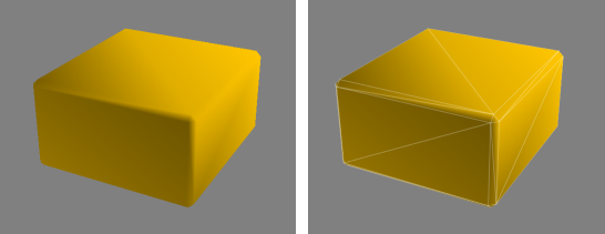
In English: vertex v will have a normal n which is the average of the combined facet normals of all connected polygons. In most situations this will look fine. But consider the situation below:
In this case the triangles that make up the thin beveled edges of the box will 'claim' much of the normal orientation. This causes the 'rounded' shading on the large flat sides of the box (problem #1).
This is then made worse because two corners of those large sides contribute 2x the facet normal (2 triangles touch the vertex), while the other two corners contribute only 1x (one triangle touches the vertex). This results into a discontinuity (the diagonal artifact in the above illustration) when shaded (problem #2).
A poor solution would be to simply align the normals to the axii of the faces when such geometry is generated (difficult to preserve) and/or to have an artist correct it by hand (labor intensive). However, we are interested in a generic solution that works for arbitrary geometry constructed from triangles (known as 'triangle soup') and n-sided polygons alike, requiring no artist intervention.
The solution is to determine the influence of each face in it's contribution to the vertex normal. The obvious way to do that is by using the surface area of each face as 'weight'. Small polygons will have little influence, large polygons have large influence.
for each face A in mesh
{
 n = face A facet normal

 // loop through all vertices in face A
 for each vert in face A
 {
  for each face B in mesh
  {
   // ignore self
   if face A == face B then skip

   // criteria for hard-edges
   if face A and B smoothing groups match {

    // accumulate normal
    if faces share at least one vert {
     n += (face B facet normal) * (face B surface area) // multiply by area
    }

   }
  }

  // normalize vertex normal
  vn = normalize(n)
 }
}
As you can see, we simply multiply the facet normal by the triangle area when we accumulate it. Since we are already normalizing the resulting vector, we don't have to do anything else. Behold:
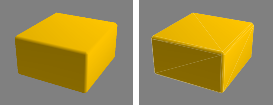
That looks much more pleasing. The beveled edges do actually still have have a slight influence over the larger sides of the box, but this is hardly noticeable in most situations (and in other cases even desirable).
While the above technique does fix the most visible problems, there's another issue that is worthwhile to consider. This problem is most noticeable on low-polygon cylindrical shapes:
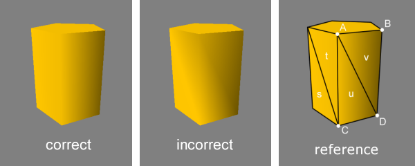
It may be hard to spot, but if you look closely you will notice a subtle shading discontinuity between
vertex A and vertex D. The three faces that influence vertex A, are faces t,
u and v. Although both faces U and V belong to the same polygon (UV), the facet normal
of that polygon contributes twice. This causes the averaged vertex normal A to point slightly to our right.
At vertex C the opposite happens, there st pulls the normal to our left.
The result being that the two vertex normals diverge when they should be parallel.
We could potentially determine which faces lie in the same plane and skip accumulating coinciding facet normals, but this works only in a small number of situations.
A robust solution is to calculate the angle of the corners of the polygons, and use that as additional weight (just like surface area) at that corners vertex. In the above figure, at vertex A, the combined angles of the two corners of faces u and v will equal the corner angle of face t.
In pseudo code, that becomes:
for each face A in mesh
{
 n = face A facet normal

 // loop through all vertices in face A
 for each vert in face A
 {
  for each face B in mesh
  {
   // ignore self
   if face A == face B then skip

   // criteria for hard-edges
   if face A and B smoothing groups match {

    // accumulate normal
    // v1, v2, v3 are the vertices of face A
    if face B shares v1 {
     angle = angle_between_vectors( v1 - v2 , v1 - v3 )
     n += (face B facet normal) * (face B surface area) * angle // multiply by angle
    }
    if face B shares v2 {
     angle = angle_between_vectors( v2 - v1 , v2 - v3 )
     n += (face B facet normal) * (face B surface area) * angle // multiply by angle
    }
    if face B shares v3 {
     angle = angle_between_vectors( v3 - v1 , v3 - v2 )
     n += (face B facet normal) * (face B surface area) * angle // multiply by angle
    }

   }
  }

  // normalize vertex normal
  vn = normalize(n)
 }
}
Here, angle is the angle in radians (or degrees*) between the two vectors of the two line segments that touch each of the three vertices in a face.
* Because we normalize the end result, the angle may be computed/stored as either radians or degrees. Only the ratio between neighboring triangle features (surface area, corner angle) contributes as weight, so the choice of angular units does not matter.Weighted vertex normals improve the appearance of virtually all geometry, and is generally superior to the traditional non-weighted average. It works because the undesired shading artifacts are displaced from large (highly visible) polygons to their smaller neighbors (less visible), and thereby guarantees improved visuals in virtually all common situations.
Since vertex normal generation is most often a design-time process, there is no impact on performance, unless the normals are re-calculated from scratch in realtime.Even though tangent space normal mapping is widely used nowadays, tangent vector use and computation requires the presence of vertex normals, and here these enhancements also improve visual quality. Tangent and bi-tangent vectors should be accumulated and weighted in parallel to vertex normals before orthogonalization for best quality.
Additionally, weighted vertex normals also allow for faux-rounded edges (smooth shaded beveled edges) without significantly increasing the polygon count, and can greatly reduce distortions of specular reflection highlights and environment mapped reflective/refractive surfaces.